Runner geometry
Flow path and channel sections matched to the cavity layout.
Hengqi engineering & manufacturing
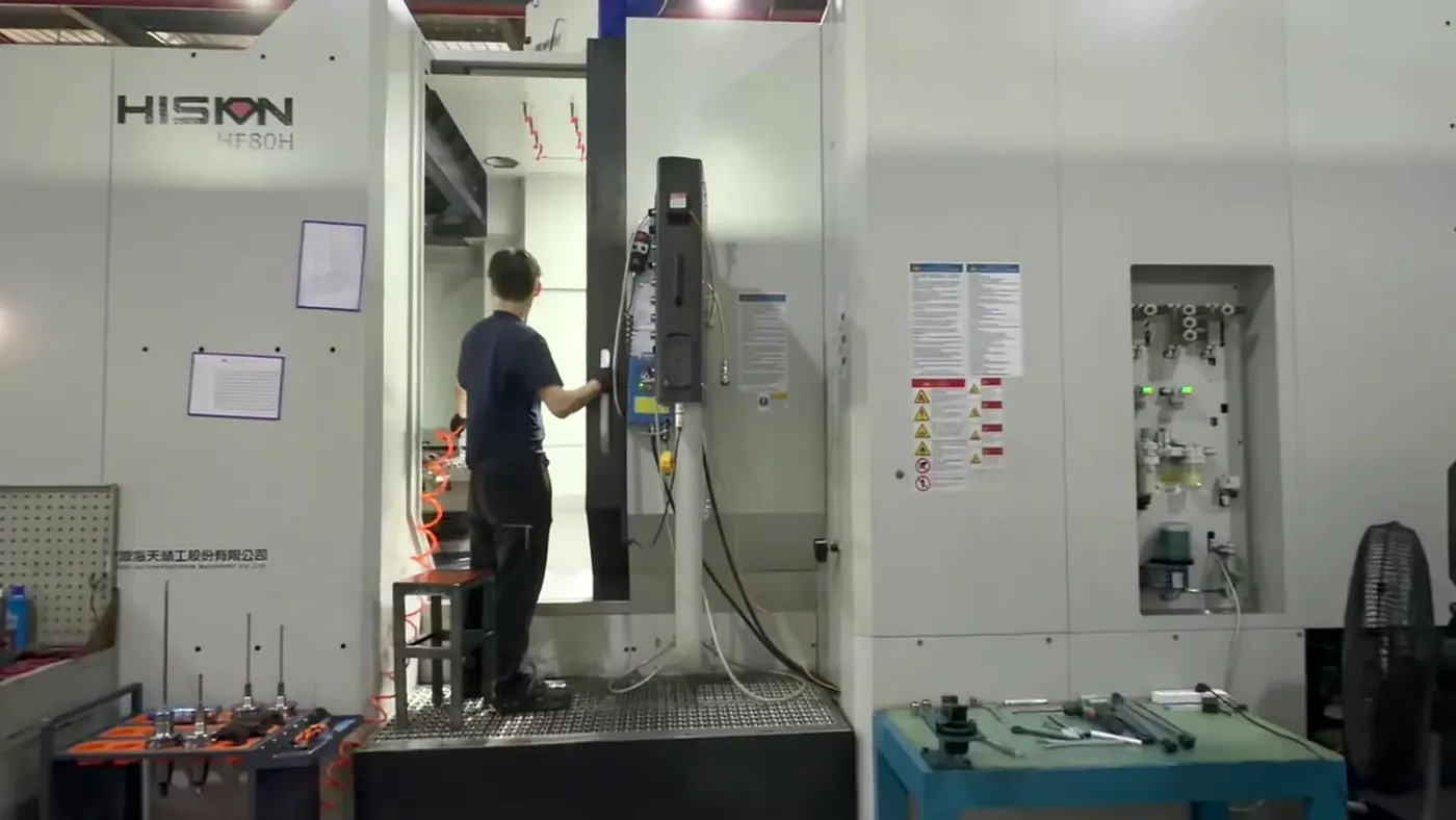
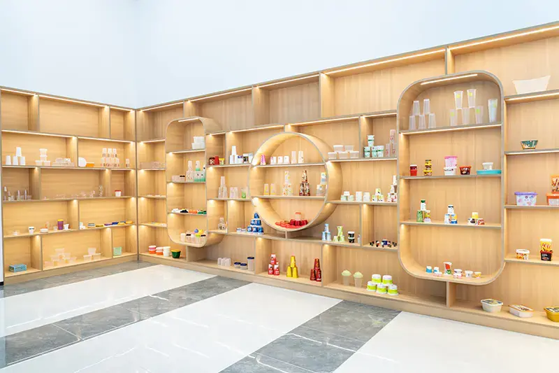
Engineering, hot runner design, precision machining, inspection, assembly and trial are managed as one delivery chain for IML and thin-wall packaging mould projects.
01 / Mould development process
The schedule connects design release, material preparation, machining, assembly and trial. A 60-day yogurt cup project is one reference—not a blanket promise. The final plan is confirmed from product complexity, cavity layout and acceptance requirements.
Capacity, wall thickness, rim, label, resin, machine and production target are reviewed before the mould structure is released.
Datum faces, plate machining, cooling layout, core steel and heat treatment are planned as one controlled manufacturing route.
Five-axis and three-axis machining protect positional relationships, fitting allowance and critical mould geometry.
Hot runner, cooling, moving interfaces and ejector systems are assembled against documented inspection points.
Filling balance, product dimensions, IML result, ejection, cycle window and samples are reviewed before delivery.
02 / Valve-gate hot runner
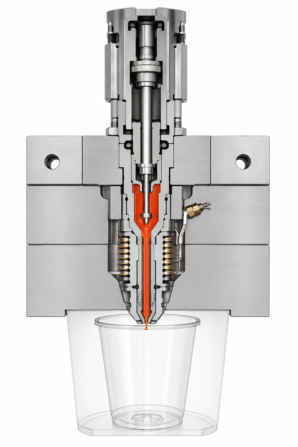
Manifold layout, nozzle selection, gate position, cooling and cavity filling are reviewed together. The goal is stable production, service access and technical response throughout the mould's working life.
03 / Flow balance engineering
Equal flow length alone does not guarantee equal parts. Hengqi reviews filling sequence, channel geometry, gate position, temperature control, cavity layout and product thickness before the design is released.
Flow path and channel sections matched to the cavity layout.
Valve sequence reviewed for filling behavior and appearance.
Temperature consistency considered alongside melt distribution.
Cavity weight, dimensions and process stability checked together.
04 / Engineering & support team
Sales, design, machining, assembly and quality teams work from the same product and production requirements. This keeps decisions traceable from the first drawing through trial samples and production support.
Geometry, wall, rim, sealing and stacking
Label area, overlap, robot and vacuum
Cavity count, cycle and hourly target
Tonnage, shot size, tie bars and automation
05 / Precision machining center
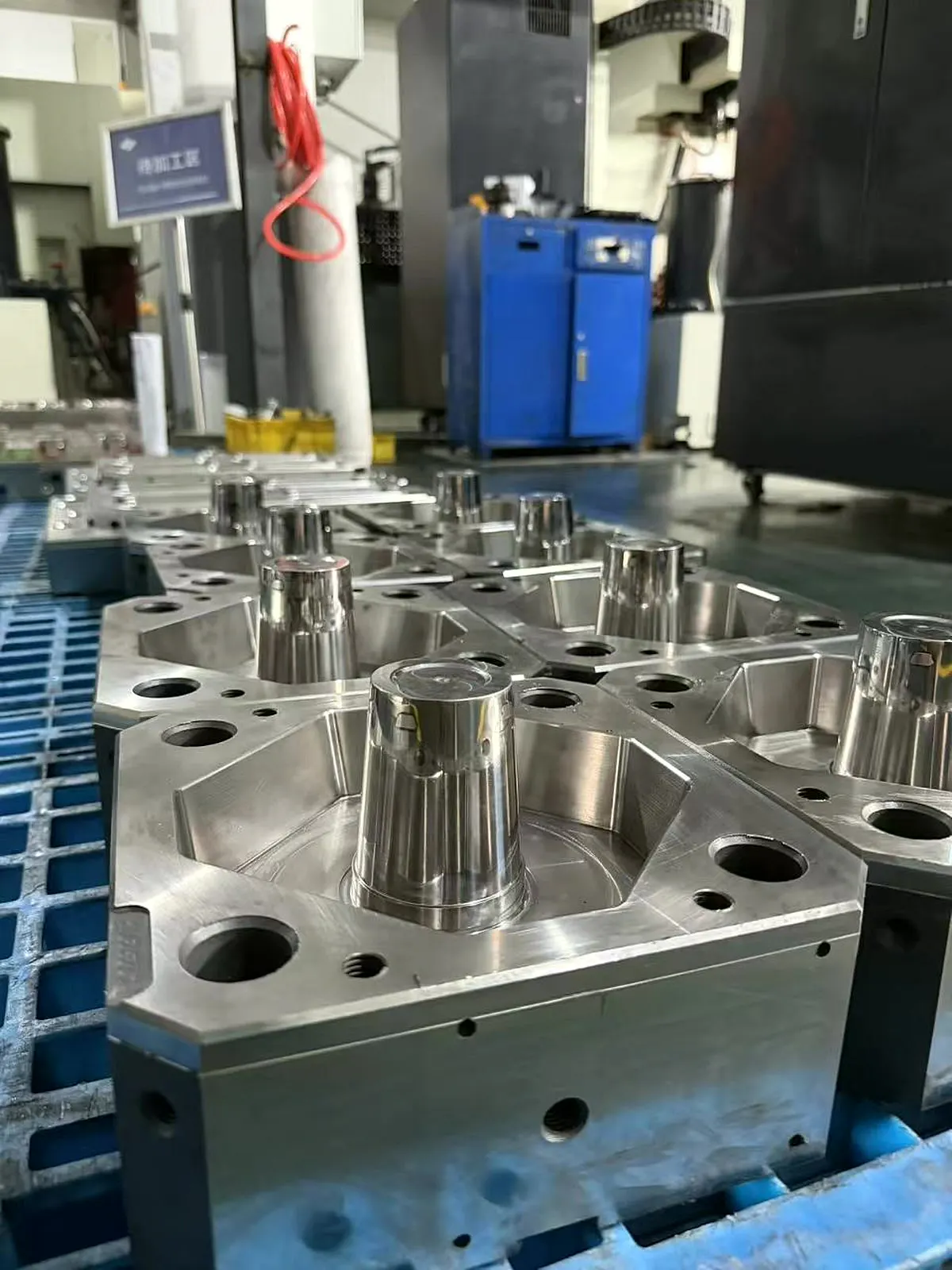
CNC, five-axis machining, EDM, grinding and precision finishing are planned around the functional datum chain of the mould. Fewer uncontrolled transfers support more stable component relationships during assembly.
Complex contours and angled features held in a coordinated setup.
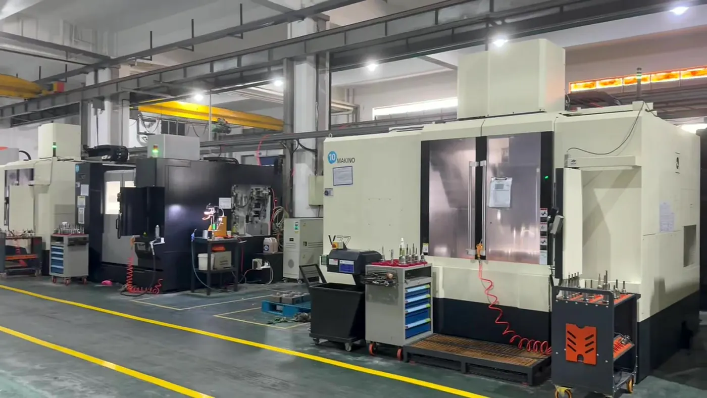
Critical components and interfaces finished against controlled allowances.
Process selection matched to geometry, material and surface requirements.
Inspection before assembly
Critical relationships verified against design intent.
06 / CMM & quality inspection
Inspection follows functional datums and assembly-critical interfaces. The purpose is not only to record isolated dimensions, but to prevent alignment, fitting and shut-off problems from entering final assembly.
A drawing, sample photo or initial concept is enough to begin. Include capacity, material, cavity target, injection machine and expected output when available.