450 ml Round Takeaway Container Mould Trial
Watch an 8-cavity 450 ml round takeaway container mould run a 5-second production trial on a 480 t injection moulding machine.
- Round container
- 8 cavities
- 5 s trial cycle
- 480 t machine
Thin-wall cycle engineering
Use real mould-trial evidence to define a production target, then verify the product, resin, machine, cooling and automation conditions that make the result repeatable.
8 cavities on a 480 t machine — recorded trial condition.
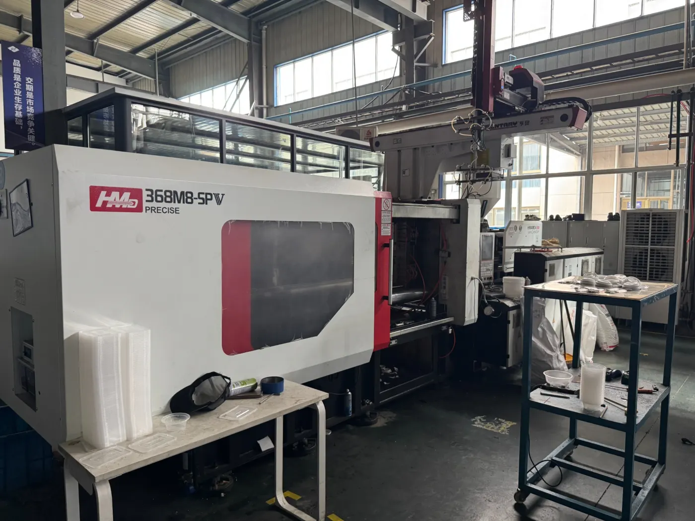
6 cavities on a 368 t machine — recorded trial condition.
8 cavities on a 420 t machine — recorded trial condition.
Confirmed only with the approved product, resin, line and acceptance method.
The 5-second and 6-second values on this page are recorded results from the specific trials shown. Hengqi does not apply those figures as blanket promises. Actual stable cycle time depends on the approved product, resin, injection machine, cooling-water conditions and robot or IML sequence.
Recorded production evidence
These results are useful engineering references because the product, cavity count and machine are shown together. They are not a universal cycle-time promise for a different part.
| Product | Cavities | Recorded trial cycle | Machine | Evidence |
|---|---|---|---|---|
| 450 ml round container | 8 | 5 seconds | 480 t | Linked mould-trial video |
| 750 ml rectangular container | 6 | 6 seconds | 368 t | Linked mould-trial video |
| 1,000 ml rectangular container | 8 | 6 seconds | 420 t | Linked mould-trial video |
Recorded figures describe the shown trials only. Actual cycle depends on product geometry and weight, resin, injection machine, mould temperature and cooling-water conditions, plus robot or take-out timing.
Watch the recorded mould trials
Each reference video documents one recorded production trial. Use the facts as engineering references, then ask us to calculate the production window for your own container.
Watch an 8-cavity 450 ml round takeaway container mould run a 5-second production trial on a 480 t injection moulding machine.
See a 6-cavity 750 ml rectangular takeaway container mould running a 6-second production trial on a 368 t injection moulding machine.
Watch an 8-cavity 1,000 ml rectangular takeaway container mould run a 6-second production trial on a 420 t injection moulding machine.
The cavity count, machine tonnage and cycle shown belong to these recorded trials. Final specifications depend on the approved product, resin, machine, cooling and automation.
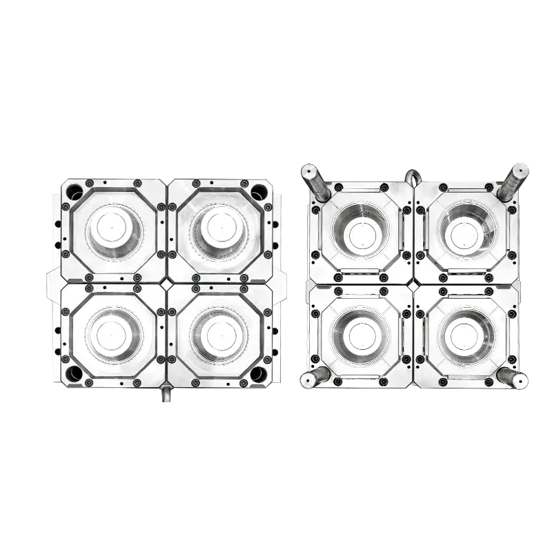
The product drawing, weight and functional criteria establish the real engineering target.
01 · Product definition
Container volume alone does not define moulding difficulty. Wall thickness, flow length, rim stiffness, bottom geometry, draft, part weight and resin grade determine how quickly the cavity can fill and when the part can be removed without deformation.
We use the approved drawing or sample to establish a target weight and functional checks such as rim roundness, stacking, lid fit and leak performance. A cycle target is meaningful only when those acceptance conditions remain stable.
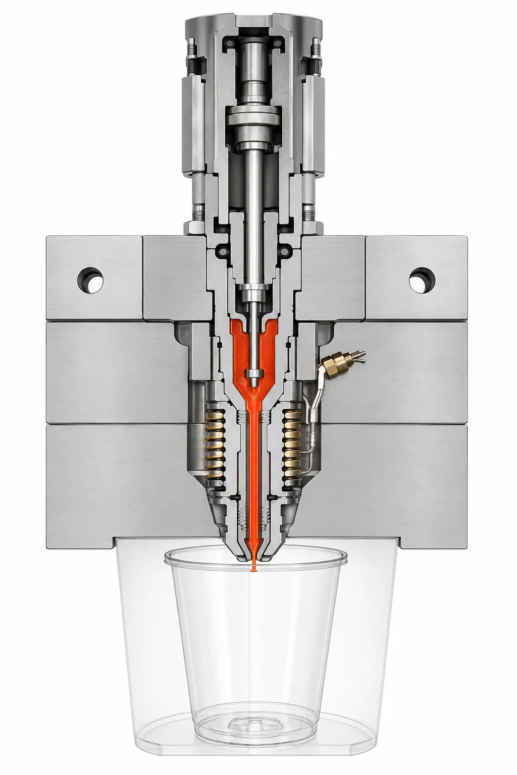
Hot-runner layout and gate control are evaluated as part of the complete moulding system.
02 · Melt delivery
In a multi-cavity thin-wall mould, runner balance, nozzle response and gate geometry affect both fill time and part-weight consistency. A fast injection command cannot correct an unbalanced melt path.
Valve-gate sequencing, manifold temperature control and gate placement are reviewed with the product geometry. The objective is stable cavity-to-cavity filling with a processing window that operators can reproduce, not one unusually fast sample shot.
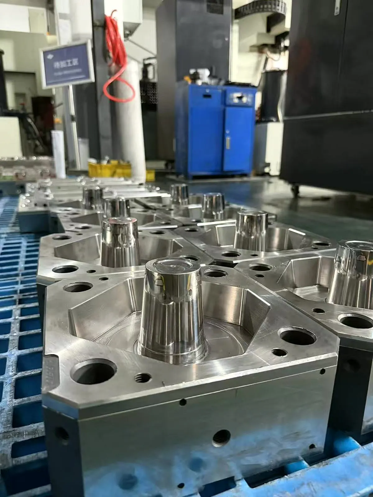
Core geometry, circuit routing and surface finish influence heat removal and release stability.
03 · Thermal control
For thin-wall packaging, cooling is often the longest part of the usable cycle. Core and cavity circuits should remove heat evenly around the rim, wall and bottom while avoiding local hot spots that lead to ovality, sink, sticking or unstable release.
Circuit layout, inlet temperature, flow rate, pressure drop and water quality all matter. The trial record is therefore reviewed together with the actual water-control conditions; copying only the seconds does not reproduce the result.
The 368 t machine shown belongs to one recorded 750 ml rectangular-container trial.
04 · Machine match
Thin-wall filling needs sufficient injection speed, pressure response and shot capacity. The mould also has to fit the tie-bar spacing and platen, while clamp force must be based on projected area and expected cavity pressure rather than a copied tonnage number.
Screw diameter, plasticising capacity, nozzle interface, opening stroke and ejector arrangement are reviewed before the mould specification is frozen. Use our machine-selection guide when the production press has not yet been confirmed.
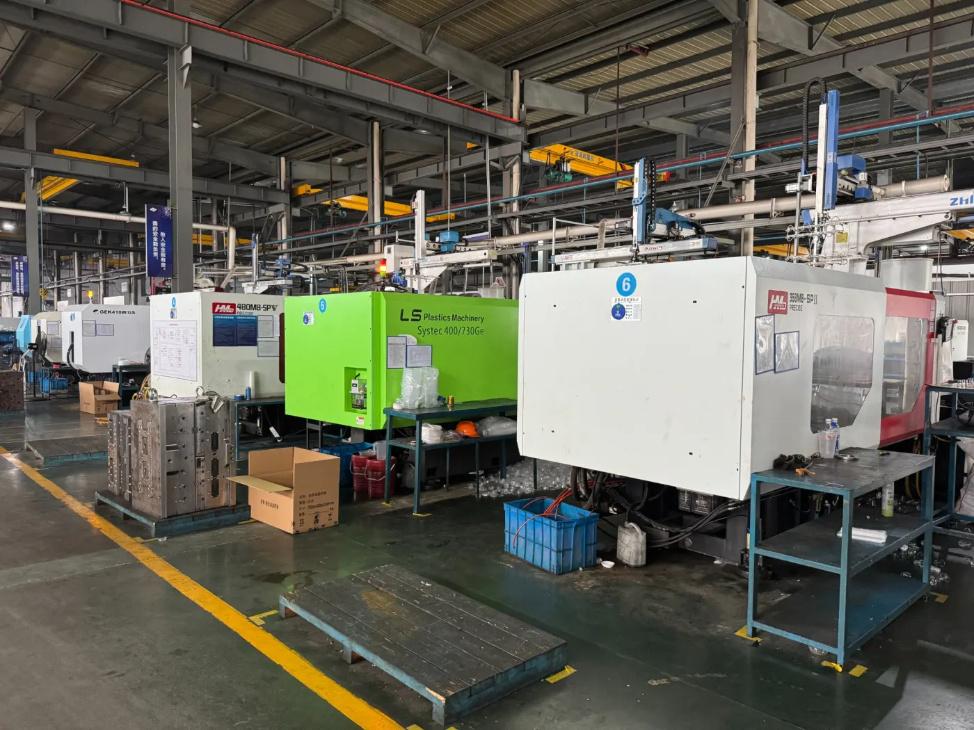
Machine, mould and take-out equipment must be evaluated as one timed production cell.
05 · Take-out and IML
Mould-open time, part release, robot entry, label placement, part take-out and mould-close confirmation form one production sequence. A laboratory dry cycle without the intended automation is not a reliable output forecast.
We ask for the robot or IML supplier, end-of-arm tooling concept, signal protocol and required opening stroke early. This prevents the mould and automation from competing for space during commissioning.

Cavity samples and functional checks make the production result measurable and repeatable.
06 · Production acceptance
A useful acceptance run records the agreed resin, machine, cooling-water conditions, robot sequence, cavity samples and processing parameters over a defined continuous period. Part weight, visual quality, dimensional stability and functional fit are checked alongside cycle time.
The approved cycle should include enough process margin for normal production variation. If a different resin, machine, chiller or automation package is used at the buyer's plant, the final stable cycle may change and should be revalidated on that line.
Buyer input checklist
A short list of accurate inputs is more useful than a generic speed request. It lets the mould, machine, cooling and automation be reviewed as one production system.
Engineering review
Send your product and line information. We will review the feasible cavity layout, machine window, cooling and automation inputs before discussing a cycle target.
Product drawing, sample photo or dimensions
Exact resin and target part weight
Required cavities and pieces per hour
Machine, water and robot or IML data
Short project review
No complete drawing yet? Send a sample photo, size or target capacity. One reply method is enough.
Technical FAQ
These answers define the information boundary for an engineering discussion. The approved product and production conditions remain decisive.
No. The 5-second figure belongs to the shown 450 ml round, 8-cavity trial on a 480 t machine. Your stable cycle depends on the approved part geometry and weight, resin, machine, cooling-water conditions and robot or IML sequence.
Common limits include flow length and wall thickness, resin flow behaviour, runner balance, injection response, uneven cooling, insufficient water flow, part stiffness at ejection and robot timing. The limiting factor must be found from the complete production cell.
Send the drawing or sample, part weight and wall target, exact resin, cavity target, intended machine data, cooling-water conditions, robot or IML plan, required output and acceptance criteria.
Agree the resin, machine, water temperature and flow, automation sequence, trial duration and quality checks before the test. Record cavity samples, part weights, defects, functional results and the complete cycle definition during a continuous run.
Not automatically. A higher cavity count can require a larger machine, more melt, more cooling and a longer robot sequence. Compare saleable output, process stability, energy, maintenance and total investment rather than cavity count alone.
Continue the technical review
Review the main food-container mould range and project options.
Open pageSee a specific round-container mould application and product details.
Open pageReview the mould, clear lid and linked production evidence.
Open pageUnderstand melt delivery, balance and gate-control decisions.
Open pageFollow the project from input review through trial and delivery.
Open pageSee how critical steel and mould dimensions are verified.
Open pageMatch clamp, shot, speed, platen and automation to the mould.
Open pageCompare products, cavities and real manufacturing applications.
Open pageCurrent page: /fast-cycle-thin-wall-mould