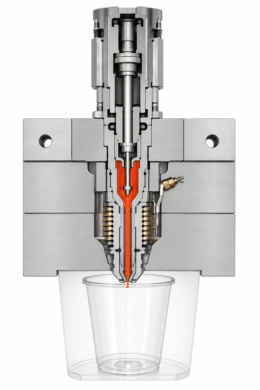
Complete multi-cavity mould with valve-gate hot runner integration

Valve-gate melt delivery

Maximum balance is engineered into the mould.

Runner layout, nozzle position, thermal control, cooling and cavity filling are treated as one connected production system for IML and thin-wall packaging moulds.

Valve-gatedControlled gate opening
Multi-cavityDistribution engineering
IntegratedRunner, cooling and mould
TrialledProduction evidence

Visual engineering record

See the people, decisions and production stages behind the claim.

Each section links a real Hengqi image with the engineering purpose it supports. Buyers can understand what is reviewed, what is manufactured and what evidence is checked before delivery.

Section view showing valve-gate hot runner integration
Valve-gate section · melt path and mould interfaces engineered together

01 / System architecture

The hot runner is part of the mould architecture—not an accessory added later.

Manifold layout, nozzle length, gate position, cavity arrangement and service access are reviewed while the mould structure is still being defined.

This creates space for cooling, wiring, pneumatic or hydraulic control and maintenance without forcing avoidable compromises at assembly.

  • Nozzle and gate positioning
  • Thermal and cooling interfaces
  • Maintenance access considered early
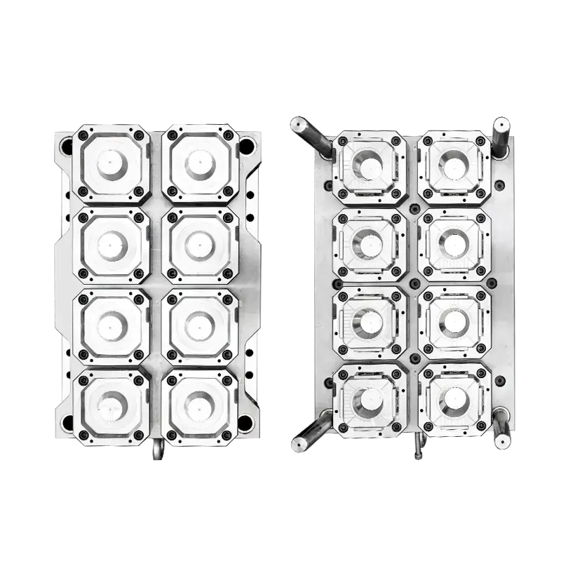
Eight-cavity packaging mould used for hot runner distribution engineering
Multi-cavity layout · distribution reviewed against the actual cavity arrangement

02 / Cavity distribution

Balance is a relationship between runner, cavity, cooling and process.

Equal runner length alone does not guarantee equal parts. Channel geometry, product thickness, gate condition, cavity layout and thermal behaviour influence the filling result.

The engineering review considers how those variables interact before the design is released.

  • Flow path and channel sections
  • Gate sequence and product appearance
  • Cooling consistency across cavities
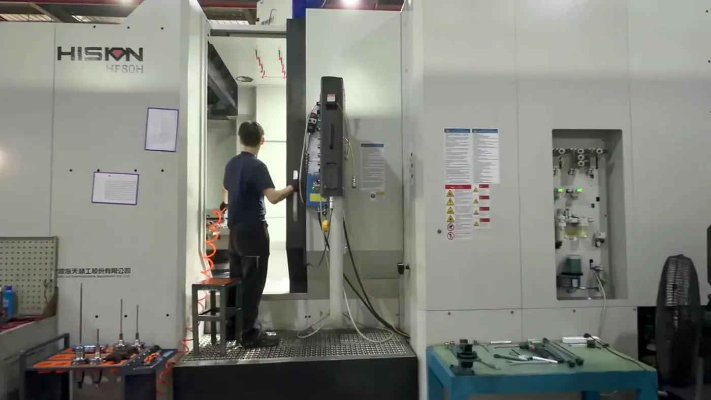
Five-axis machining used to produce coordinated mould geometry
Coordinated machining · geometry prepared for repeatable system assembly

03 / Precision integration

Nozzle and manifold interfaces depend on controlled component geometry.

Hot runner performance relies on the positional relationship between the manifold, nozzles, gates, seals and mould plates.

Machining and inspection therefore protect the datums and assembly interfaces that keep the flow system aligned.

  • Datum-controlled positioning
  • Stable fitting allowances
  • Gate and cooling geometry protected
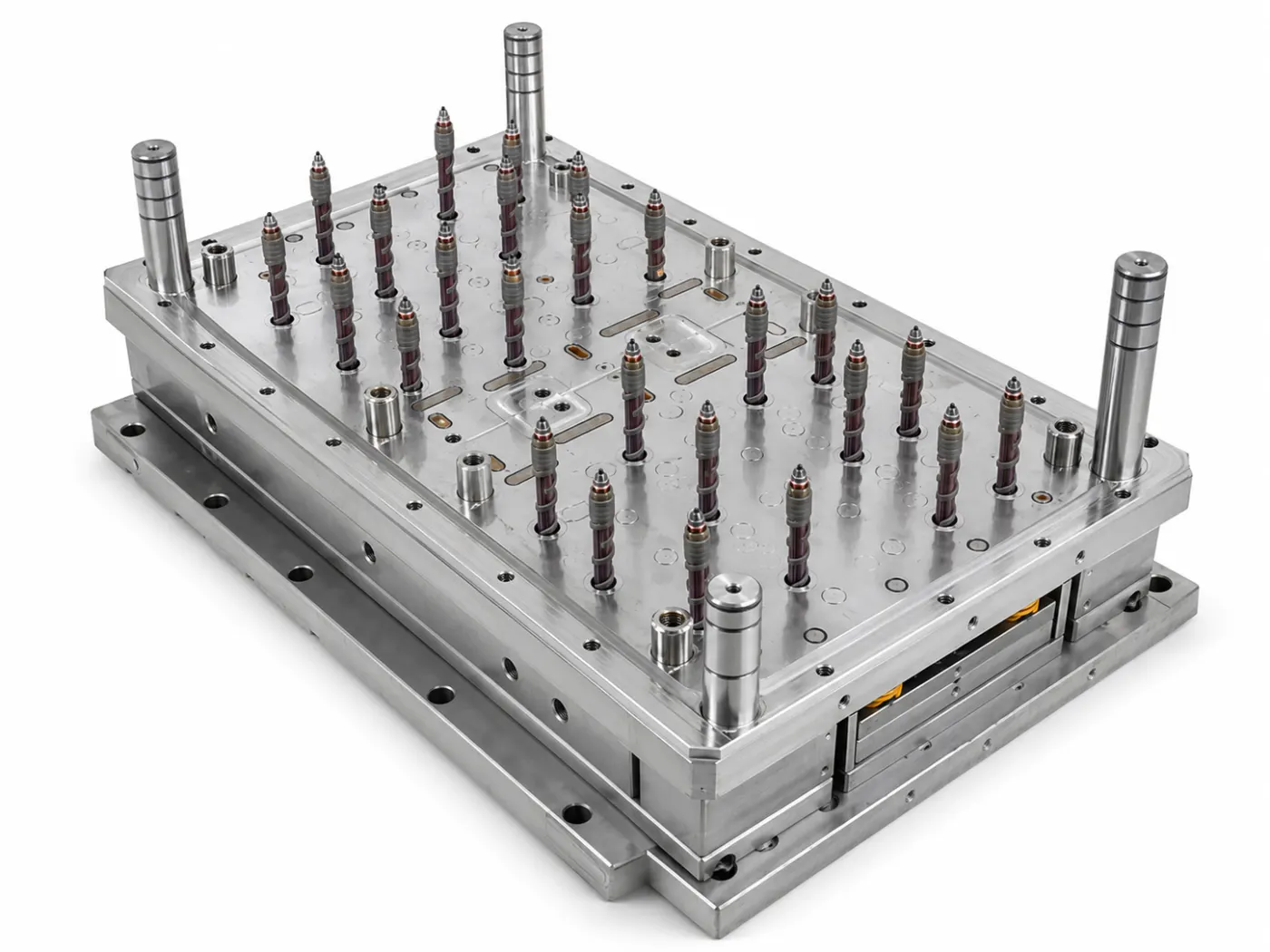
Complete packaging mould after hot runner assembly
Complete assembly · melt delivery and mould functions checked together

04 / Mould assembly

The complete mould is assembled and checked as one functional system.

Valve movement, heating, sensing, sealing, cooling and mould movement are checked together before production validation.

The same project team can respond to runner, mould and process questions without splitting responsibility between unrelated suppliers.

  • Valve-gate movement
  • Heating and sensor checks
  • Cooling and mechanical clearance
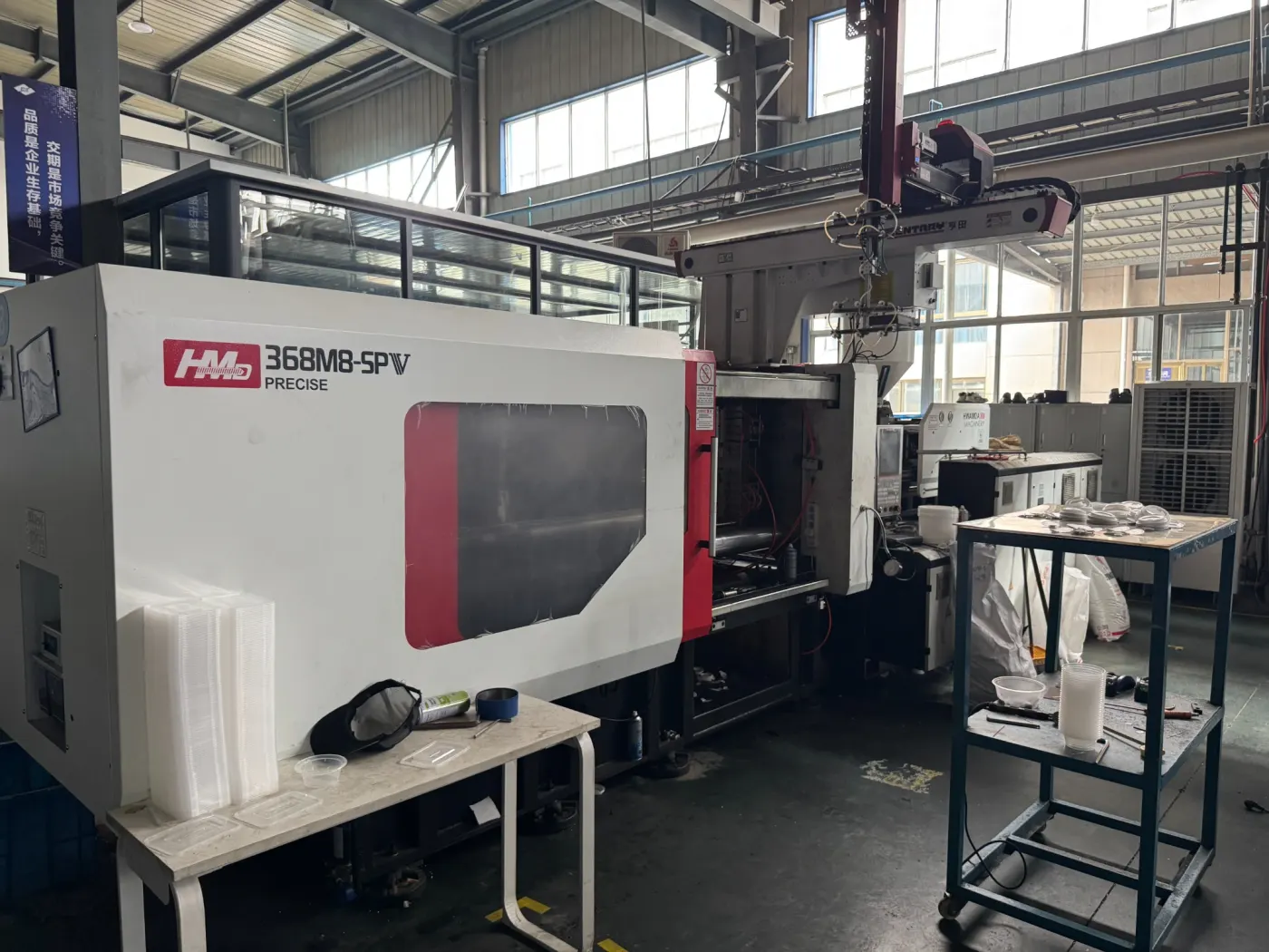
High-speed injection moulding machine used for thin-wall mould trials
High-speed trial · cavity behaviour checked under a production-relevant condition

05 / Trial validation

Production evidence decides whether the balance is useful.

The mould trial reviews filling sequence, cavity weight, part appearance, dimensions, gate result and process stability.

Findings are returned to the hot runner, mould and process teams so adjustments address the complete system instead of one isolated symptom.

  • Filling and cavity-weight review
  • Gate appearance and product quality
  • Stable thermal and process window

Flow balance engineering

Design first. Integrate directly. Validate as a system.

The critical path stays connected from product review through assembly and production trial.

01

Map the part

Product thickness, appearance, gate limits and cavity layout define the flow problem.

02

Design the path

Manifold, channels, nozzles and valve control are matched to the real mould structure.

03

Control interfaces

Machining and inspection protect the datums required for sealing and gate alignment.

04

Validate filling

Trial evidence compares cavity behaviour and returns findings to engineering.

Start with the production requirement

Share the product and production line. We will map the melt-delivery requirement.

Hot runner selection becomes more reliable when the gate, machine, resin, label and output conditions are known.

Send project information
01Product drawing, resin and part weight
02Cavity count and cavity arrangement
03Gate mark and appearance restrictions
04IML label area and robot timing
05Machine shot size and injection performance
06Preferred hot runner brand or plant standard

Buyer questions

Clarify the project before steel is committed.

Why is the hot runner reviewed together with the mould design?

Runner geometry, gate position, cooling, cavity layout, product appearance and service access affect one another. Reviewing them as one system reduces late design conflicts.

Can Hengqi integrate a customer-specified hot runner brand?

Yes. The project can be engineered around the agreed hot runner standard when the buyer's plant has a preferred brand or maintenance requirement.

How is cavity-to-cavity balance checked?

The trial plan can compare filling sequence, part weight, appearance, dimensions, temperature behaviour and process stability across cavities under the agreed production condition.