Injection molding machine for thin wall containers with mould and automation line

Machine and mould matching

Selecting an Injection Molding Machine for Thin Wall Containers

Match clamp force, shot size, injection performance, mould envelope, cooling and robot or IML interfaces before the machine or mould specification is approved.

Clamp-force basis
Area × pressure

All cavity and runner projected area, estimated cavity pressure and an agreed safety margin.

Shot-size basis
Part + runner

Total shot mass or volume plus a practical injection-unit operating margin.

Thin-wall filling
Speed + response

Enough flow rate, pressure and acceleration to fill before the melt skin freezes.

Cell compatibility
Physical + signals

Tie bars, platen, stroke, nozzle, ejector, robot, IML and safety interlocks.

This guide is a selection framework, not a machine-size quotation. Final values must be calculated from the approved part, resin, cavity and runner layout, mould drawing, required output and exact machine/automation datasheets.

Selection framework

Match the production cell before steel specifications are frozen

Machine tonnage is only one line in a complete compatibility review. Use this sequence to expose physical, processing and automation conflicts before mould manufacturing begins.

DecisionEngineering basisBuyer data neededRisk if missed
Clamp forceProjected area × estimated cavity pressure + safety marginPart drawing, cavities, runner and resinFlash, platen strain or unnecessary machine cost
Shot and plasticisingTotal part/runner mass, resin density and cycle demandPart weight, runner type, resin and target cycleUnstable dosing, long recovery or material residence
Injection performanceRequired flow rate, pressure, acceleration and repeatabilityWall, flow length, resin and fill targetShort shots, high stress or narrow process window
Mould fitTie bars, platen, daylight, stroke, nozzle and ejectorDimensioned machine datasheetMould cannot install, open or eject safely
AutomationRobot entry, EOAT, IML, signals and sequence timeRobot/IML drawings and interface listInterference, slow sequence or unsafe commissioning

The final machine recommendation must use one consistent unit system and the approved product, resin, cavity layout and mould concept. Hengqi reviews the calculation with the machine and automation suppliers when required.

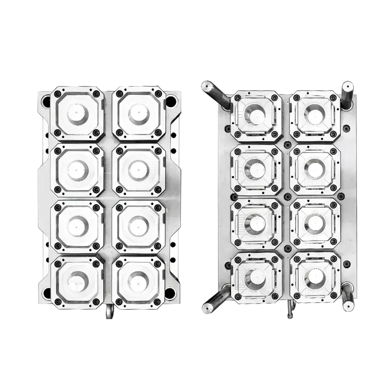
Eight-cavity thin wall container mould used for projected-area and clamp-force review

Cavity count and full projected area are evaluated before the required clamping window is selected.

01

01 · Clamp-force calculation

Calculate tonnage from projected area and cavity pressure

Clamp force is estimated from the total projected area of all moulded cavities and the runner, multiplied by an appropriate cavity-pressure estimate and safety factor. The calculation must use compatible units and account for the selected resin, wall thickness, flow length, gate system and process window.

Catalogue tonnage alone does not prove suitability. Too little clamp force can produce flash or unstable dimensions; excessive oversizing can raise machine and energy cost without solving injection-speed, shot-size or mould-fit constraints.

  • All cavities plus runner projected area
  • Resin- and geometry-based pressure estimate
  • Documented safety margin
  • Machine platen load and clamp window
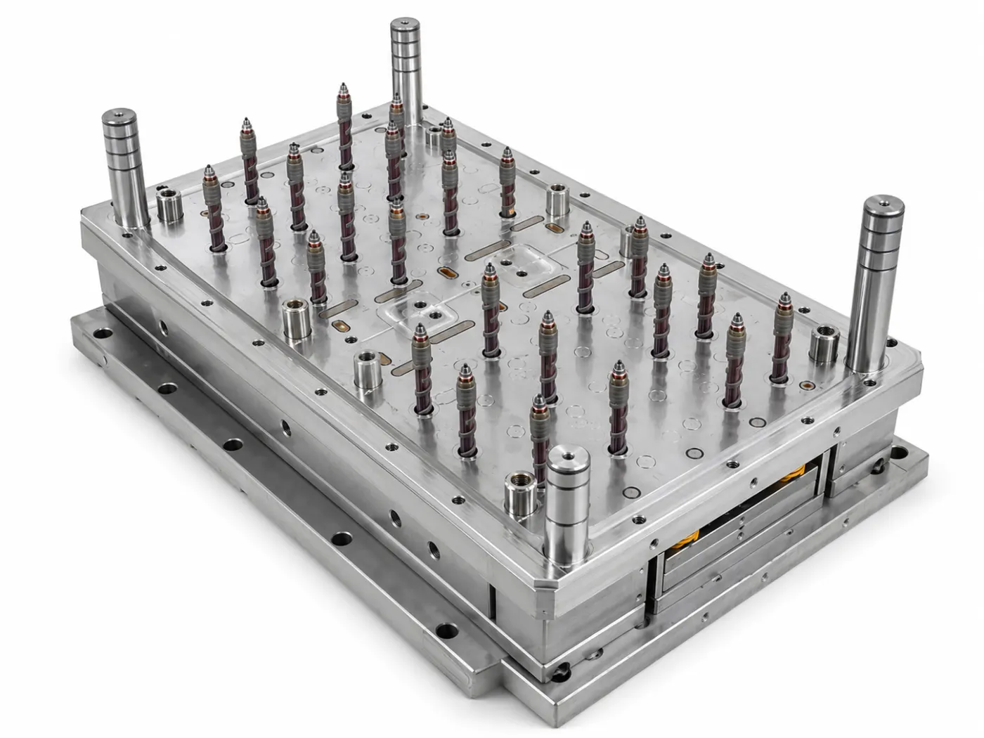
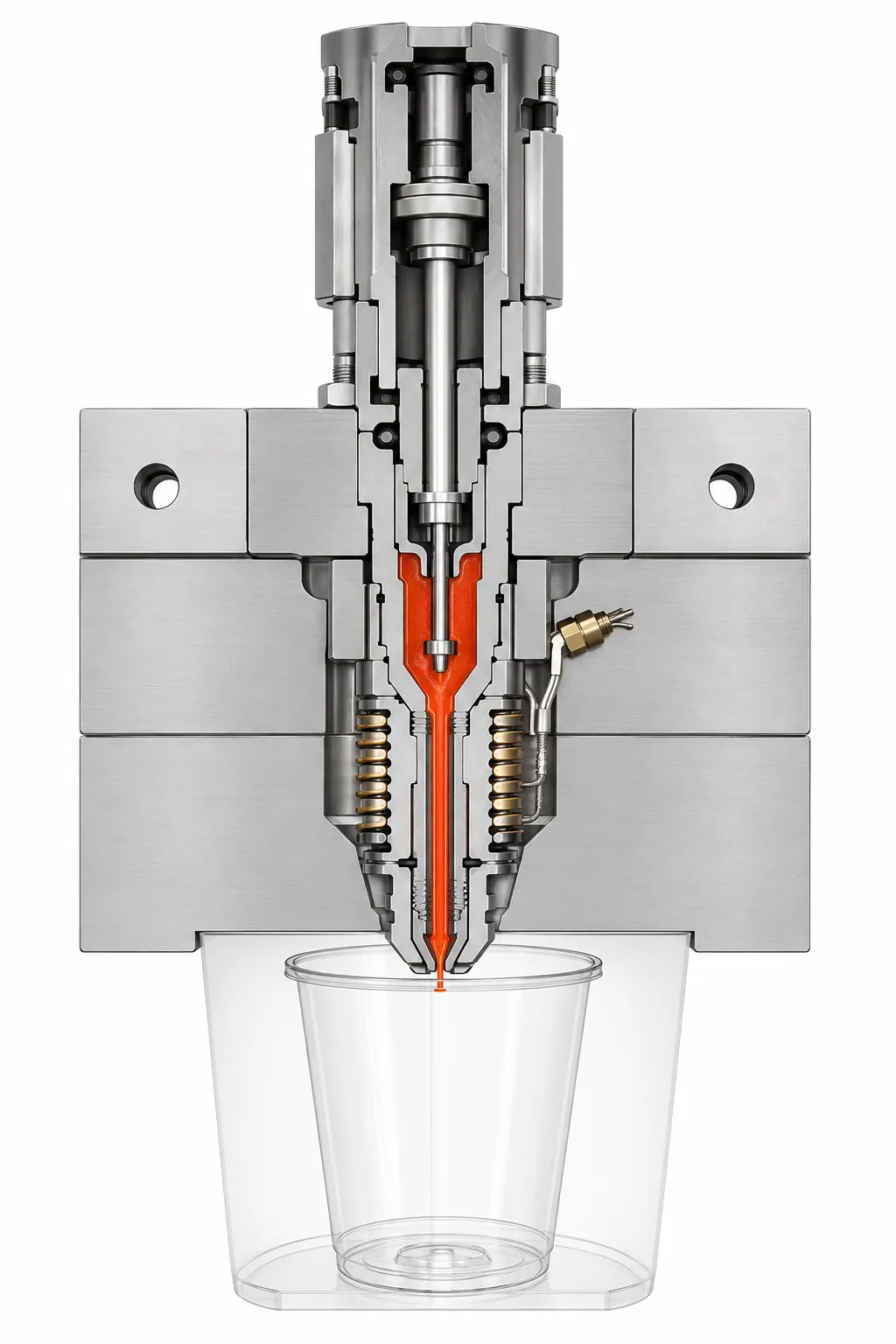
Hot runner section considered when calculating thin wall mould shot volume

Hot runner or cold runner changes the total shot calculation and the required injection-unit operating point.

02

02 · Injection unit

Choose shot size, screw diameter and plasticising reserve together

Start with finished-part weight multiplied by cavity count, then add the cold-runner mass when applicable. Convert mass and volume with the actual resin density and keep the shot within the machine manufacturer's recommended working range rather than at an extreme end of barrel capacity.

The screw must also recover the next shot inside the target cycle without excessive back pressure, melt temperature or residence time. A large nominal shot capacity does not guarantee fast, uniform plasticising for PP packaging production.

  • Part mass × cavity count
  • Runner mass and resin density
  • Recommended shot utilisation range
  • Plasticising rate within target cycle
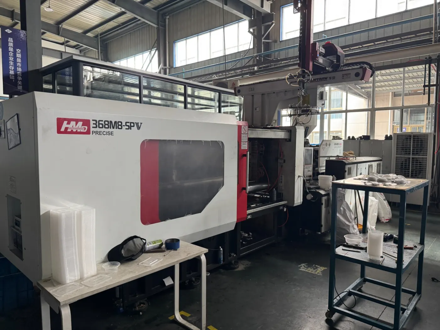
High-speed injection moulding machine used for a rectangular thin wall container trial

A recorded 368 t trial is evidence for that specific mould and machine combination, not a universal tonnage recommendation.

03

03 · Filling performance

Specify injection speed, pressure and response — not drive type alone

A thin wall freezes quickly, so the injection unit needs enough volumetric flow, pressure reserve and acceleration to reach a controlled fill profile. Screw diameter affects both available injection rate and pressure; the supplier should compare actual values rather than relying on a marketing label such as high speed.

Electric, hydraulic and hybrid machines can each be suitable when correctly specified. Repeatability, pressure transfer, metering stability and control response should be tested with the intended mould and resin. The drive architecture is a comparison factor, not the complete selection method.

  • Maximum and usable injection rate
  • Pressure reserve at the chosen screw
  • Acceleration and transfer response
  • Shot-to-shot weight repeatability
Complete thin wall packaging mould prepared for injection-machine fit verification

A dimensioned mould envelope must be checked against the exact machine platen and opening geometry.

04

04 · Physical interface

Confirm tie bars, platen, daylight and every mould interface

The mould base must pass between the tie bars and be supported by the platen with suitable mounting points. Check minimum and maximum mould thickness, daylight, opening stroke, ejector stroke and force, locating-ring diameter, nozzle radius, nozzle reach and sprue-bush interface.

Opening stroke is defined by the product, ejection method and robot path, not only by mould height. Use signed machine drawings where possible, because model names and nominal tonnage may cover more than one platen or injection-unit configuration.

  • Tie-bar spacing and platen dimensions
  • Mould thickness, daylight and opening stroke
  • Nozzle, locating ring and sprue interface
  • Ejector layout, stroke and force
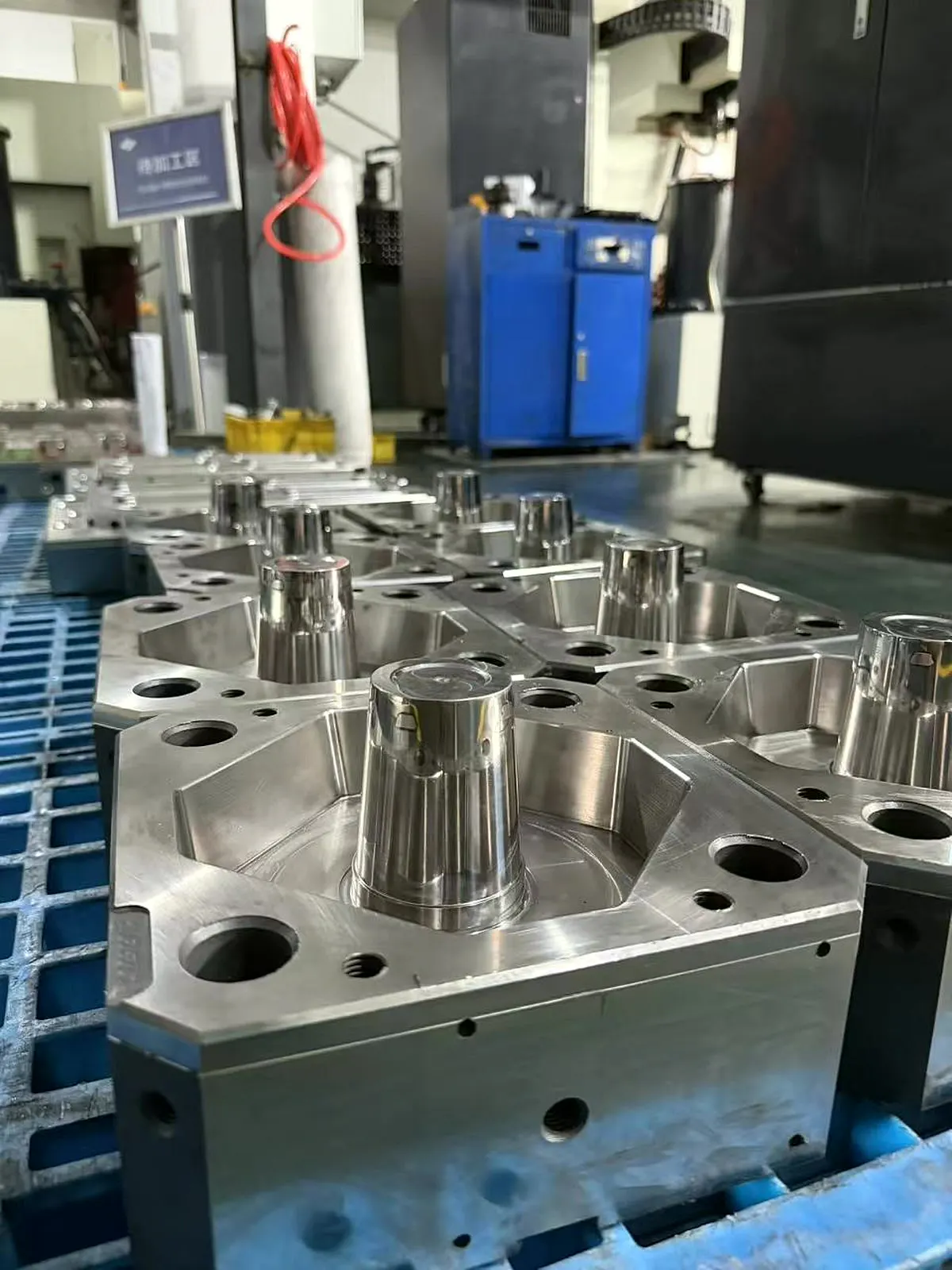
Precision container mould cores with cooling features for production-cell utility review

Cooling demand links mould geometry to the plant chiller, manifold and water-distribution system.

05

05 · Cooling and utilities

Machine selection is incomplete without the real cooling system

The chiller, manifold, hose size, connector restriction and water quality determine the temperature and flow available at the mould. A fast machine cannot compensate for insufficient heat removal or unbalanced circuits.

Record available inlet temperature, pressure, flow and plant-water specification. Confirm hot-runner controller zones, electrical supply, air requirements and hydraulic core-pull connections so the mould can be commissioned without temporary interfaces.

  • Water temperature, pressure and flow
  • Chiller capacity and manifold layout
  • Hot-runner zones and power supply
  • Air and hydraulic service connections
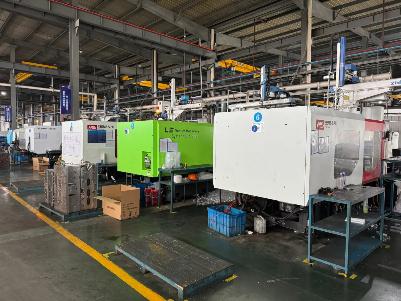
Injection moulding machine and automation cell for thin wall container production

Mould, machine, robot and IML equipment operate as one interlocked production cell.

06

06 · Robot and IML interface

Define robot clearance, IML signals and sequence time before launch

For automatic take-out or in-mould labelling, the robot supplier needs the mould-open position, product release point, safe entry envelope and end-of-arm tooling load. The machine must provide enough opening, speed and access without placing the mould or robot in an unsafe condition.

Agree the machine–robot signal list, safety interlocks, label-presence confirmation, vacuum and static requirements, reject handling and restart sequence. The complete robot and IML motion belongs in the production-cycle estimate.

  • Robot entry envelope and EOAT load
  • Mould-open and ejector positions
  • Signal list and safety interlocks
  • Label, take-out, stacking and reject sequence
Thin wall moulded packaging parts prepared for production-line acceptance inspection

Saleable output and process margin are more useful acceptance measures than one fastest cycle.

07

07 · Acceptance test

Prove the selected line with a continuous, measured trial

Machine matching should be accepted with the approved mould, resin, water conditions and automation sequence. Record fill profile, pressure use, cushion, recovery time, clamp setting, part weight, cavity balance, defects, dimensions and functional checks during a defined continuous run.

The goal is not to operate every parameter at its maximum. A robust production cell keeps enough pressure, speed, clamp, cooling and timing margin for normal variation while meeting the agreed saleable-output target.

  • Agreed resin and complete automation
  • Continuous run and cavity samples
  • Recorded process utilisation and recovery
  • Saleable output plus quality checks

Buyer input checklist

Use this buyer checklist with the machine and mould suppliers

Ask both suppliers to sign off the same product, mould-envelope, injection-unit and automation data. That shared worksheet prevents gaps hidden by a nominal machine-tonnage number.

01

Product load

  • Drawing, dimensions and total projected area
  • Part weight, wall thickness and flow length
  • Exact resin grade, MFI and density
  • Cavity count, runner system and output target
02

Injection and clamp

  • Clamp force and platen load limit
  • Shot volume, screw diameter and plasticising rate
  • Injection rate, pressure and response
  • Control repeatability and process-data export
03

Mould envelope

  • Tie-bar and platen dimensions
  • Mould thickness, daylight and opening stroke
  • Nozzle radius/reach and locating ring
  • Ejector pattern, stroke and force
04

Robot and IML

  • Robot model, entry path and EOAT drawing
  • Machine–robot signal and safety interface
  • IML label, static and vacuum requirements
  • Take-out, stacking, reject and restart sequence

Engineering review

Send the product and machine datasheet for a compatibility review

If you already own the machine, we can review the proposed mould against its platen, injection unit, stroke, utilities and automation. If the machine is not selected, send the product target and required output first.

Approved part drawing, weight, wall and resin

Cavities, runner concept and required output

Full machine datasheet and platen drawing

Robot/IML drawing, utilities and signal list

Send the same inputs on WhatsApp

Short project review

Get a focused mould quotation

No complete drawing yet? Send a sample photo, size or target capacity. One reply method is enough.

Your details are used only to review and reply to this mould project.

Technical FAQ

Questions buyers ask before steel is ordered

These answers define the information boundary for an engineering discussion. The approved product and production conditions remain decisive.

How is clamp force estimated for a thin wall container mould?

Use the total projected area of every cavity and the runner, multiply it by an appropriate cavity-pressure estimate, then apply an agreed safety factor using one consistent unit system. Resin, wall thickness, flow length, gate design and cavity count affect the pressure assumption.

What shot-size margin should the injection unit have?

Calculate all moulded parts plus cold-runner material, convert mass and volume using the actual resin density, and check the result against the machine manufacturer's recommended shot-utilisation range. Also confirm that the screw can plasticise the next shot within the cycle without excessive residence time.

Is an all-electric machine always best for thin wall containers?

No. Electric, hydraulic and hybrid machines can all work when their injection rate, pressure, acceleration, clamp, shot capacity, mould envelope and automation interface match the project. Compare measured capability and support, not drive type alone.

Which machine dimensions must be checked against the mould?

Check tie-bar spacing, platen dimensions and mounting pattern, minimum and maximum mould thickness, daylight, opening stroke, ejector pattern/stroke/force, locating ring, nozzle radius, nozzle reach and sprue-bush interface.

What must be agreed for a robot or IML system?

Agree the entry envelope, end-of-arm tooling, opening and ejector positions, signal list, safety interlocks, label confirmation, vacuum/static services, take-out and stacking sequence, reject handling and cycle time.